Tech4POD - Equivalent Text Description
Procedures for OI Population
Brief Description:
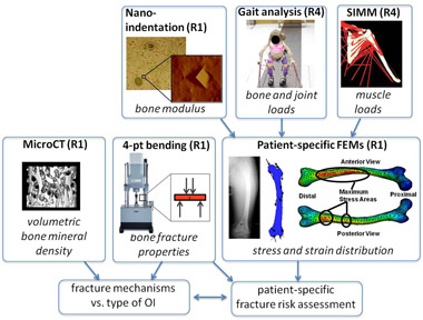
Picture shows the relation of different parts for patient-specific fracture risk assessment.
Essential Description:
This diagram illustrates how various research projects (e.g. R1 and R4) within the RERC will integrate to create Patient-specific finite element methods (FEMs) of bones to assess patient-specific fracture risks. This is linked to fracture mechanisms vs. type of Osteogenesis Imperfecta as measured by two techniques in research project R1.
Detailed Description:
The chart shows interactions between eight boxes representing procedures for OI populations. The first box at the left is “Nano-indentation (R1)” includes an image of bone composition at a microscopic level, and a second image of a closer look at a component of the bone composition. The images are labeled “bone modulus”. A second image, “Gait analysis (R4)”, includes an image, labeled “bone and joint loads”, of a little girl using bilateral forearm crutches down a walkway with ball sensors attached to both her legs. A third box, “SIMM (R4)”, includes a graphical line representation of the muscles in the shoulder. Each muscle is represented by a single line with reference points provided by the humerus and scapula. This image is labeled “muscle loads”. Each of these images has arrows to a box labeled “Patient-specific FEMs (R1)” with an x-ray image of a laterally bowing femur, a blue graphical representation of a femur with multiple arrows indicating stress lines and directional forces on the bone, and an anterior and posterior femur mapping the stress areas. These images are labeled “stress and strain distribution”. Patient-specific FEMs (R1) feeds into a bottom “patient-specific fracture risk assessment” box, which interacts with the other bottom box, “fracture mechanisms vs. type of OI”. “4-pt bending (R1)” influences both of the ultimate boxes (fracture mechanisms and fracture risk assessment). The 4-pt bending has a picture of a mechanical stress test machine with point loading and an expanded box showing a rectangle with a small fracture and four stressors. This image is labeled “bone fracture properties”. The last box, “MicroCT (R1)” shows a graphic of microscopic bone with numerous holds throughout and is labeled “volumetric bone mineral density”. This image feeds the outcome box of “fracture mechanisms vs. type of OI”.