Tech4POD - Equivalent Text Description
Configuration of proposed biplane fluoroscopy system
Brief Description:
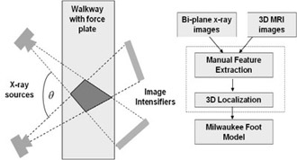
Diagram shows the configuration of a proposed biplane fluoroscopy system and analysis method.
Essential Description:
This diagrams the proposed biplane fluoroscopy setup that will allow for 3D localization. A darkened area between two x-ray sources illustrates the area where 3D localization will occur. An accompanying flow chart describes the process of integrating the bi-plane x-ray images with 3D MRI images to form the Milwaukee Foot Model.
Detailed Description:
Two devices labeled “X-ray sources” in the upper and lower left corners of the image resemble cameras with a rectangular base and a protruding triangular lens. Each has dotted lines that project away from the devices and create an “X” shape, overlapping in the middle of a long rectangle labeled “Walkway with force plate” and continuing to end on rectangular objects labeled “Image Intensifiers”. To the right of the image, a flowchart consists of five boxes and flows downward. At the top, two boxes positioned side-by-side contain the words “Bi-plane x-ray images” and “3D MRI images”. Both lead into “Manual Feature Extraction”, which leads to “3D Localization, which leads to “Milwaukee Foot Model”.